Deployment Architecture
The following diagram shows a typical deployment model for the components of the a9s Data Services Framework.
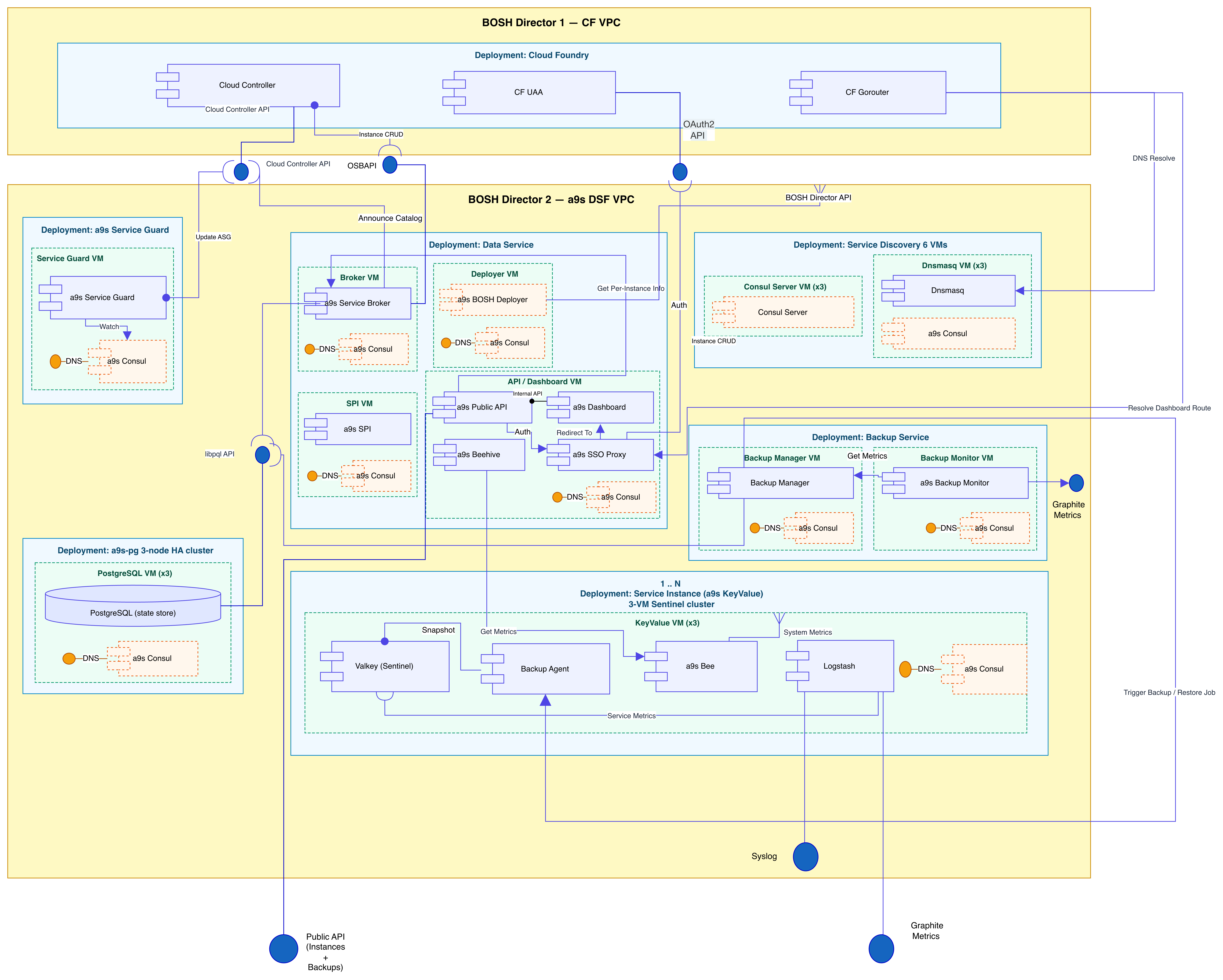
The notation follows a hierarchy of BOSH Deployments, which are manifest-based descriptions of VMs together with their disk, network, and configuration. BOSH manages all VMs within a deployment as an atomic group. Within each deployment, one or more VMs are shown, each running one or more colocated components (processes). The number of VMs varies per deployment and is indicated in the diagram accordingly.
In a typical setup, the application platform (Cloud Foundry) is managed by a separate BOSH Director from the a9s DSF. This separation is indicated by two distinct frames labeled "BOSH Director". Cloud Foundry and the a9s DSF interact through specific interfaces, shown using UML 2.0 lollipop notation. Since Cloud Foundry components are outside the scope of the a9s DSF offering, they are not expanded in the diagram.
For a full reference of the installation steps that realize this deployment model, see the Installation Guide. For the network topology and IP addressing design, see Network topology. For a full list of required ports between components, see Required Ports.