Network Topology
The diagram below illustrates the network topology of the a9s Data Services Framework across availability zones.
The architecture shown represents a recommended approach based on best practices. Actual deployments may require different configurations depending on the specific environment, infrastructure, and operational requirements.
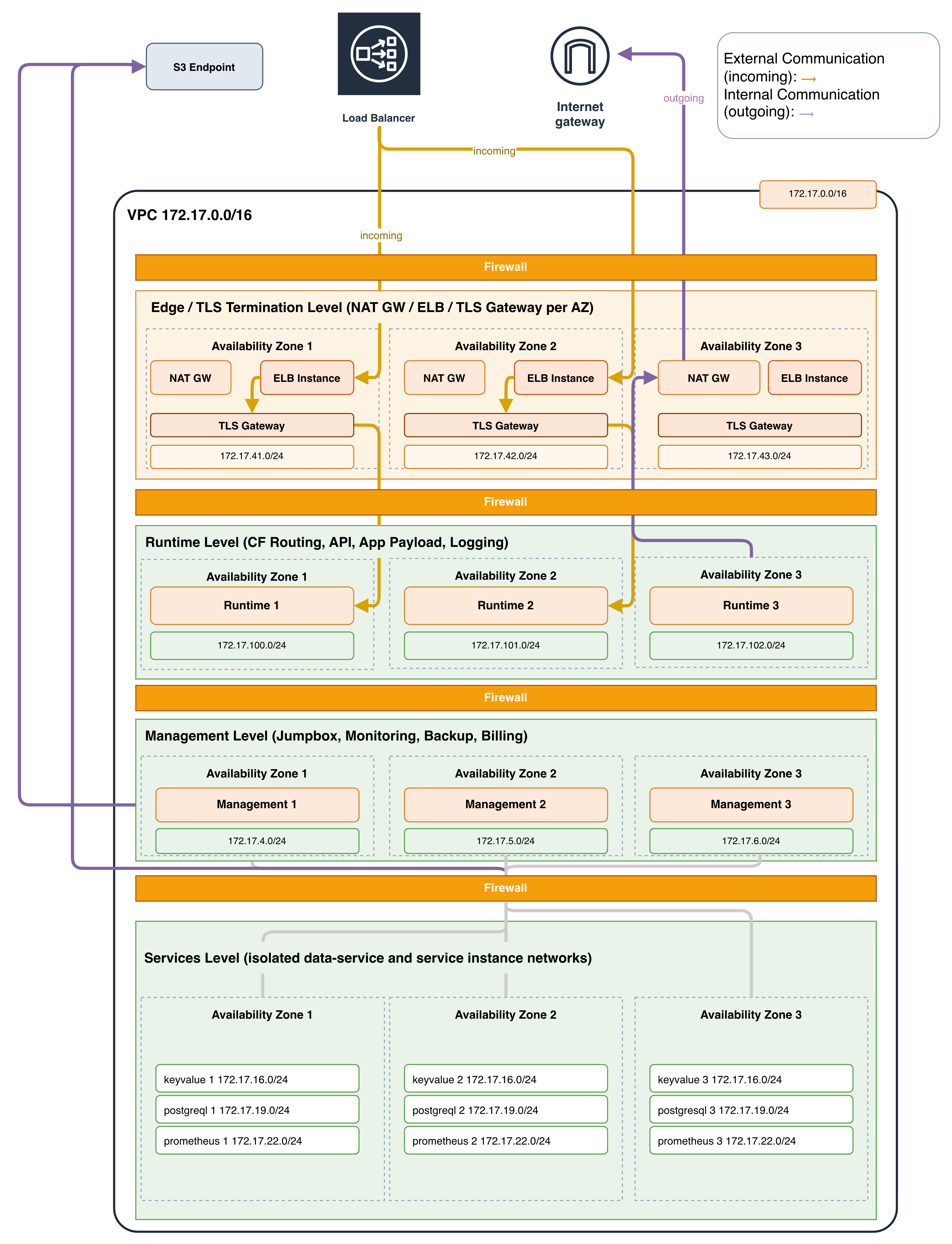
The topmost layer handles the transition from public to private traffic, where TLS termination and load balancing take place. The second layer corresponds to the components that are publicly consumable. The third layer hosts a9s DSF components that perform operations across multiple Data Services and multiple Service Instances. The last layer is where the Data Services and their Service Instances are placed.
Deployments are distributed across multiple availability zones at every layer. High availability is a first-class consideration in the framework's design.
For a complete list of required ports between components, see Required Ports.